Gearbox designer · VRT · Sep 2025 to Aug 2026

Stepped planetary gearbox

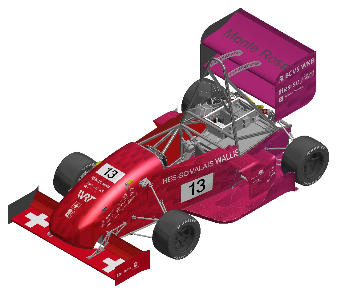
One in each wheel of the Valais Wallis Racing Team’s 2026 car. I was its only designer, from a blank page to assembly, beside my full-time studies, working with the team’s hub designer and the machine shop.

Available from June 2027

12.6: 1reduction, motor to wheel
403Nmtorque at each wheel
120km/htop speed
4competitions across Europe

The brief

A new car, a new gearbox.

The gearbox sits in the wheel hub, between the motor and the wheel. For 2026 the team changed three things around it, and the old gearbox could not be adapted.

  • 10-inch wheels instead of 13: far less room inside the wheel. So a new architecture, with the planet bearings now sitting on the shafts.
  • Four-wheel drive instead of two driven wheels: every drivetrain part doubled, on a car that had to get lighter.
  • A new motor, off the shelf, with a female output: the sun gear had to plug straight into it.
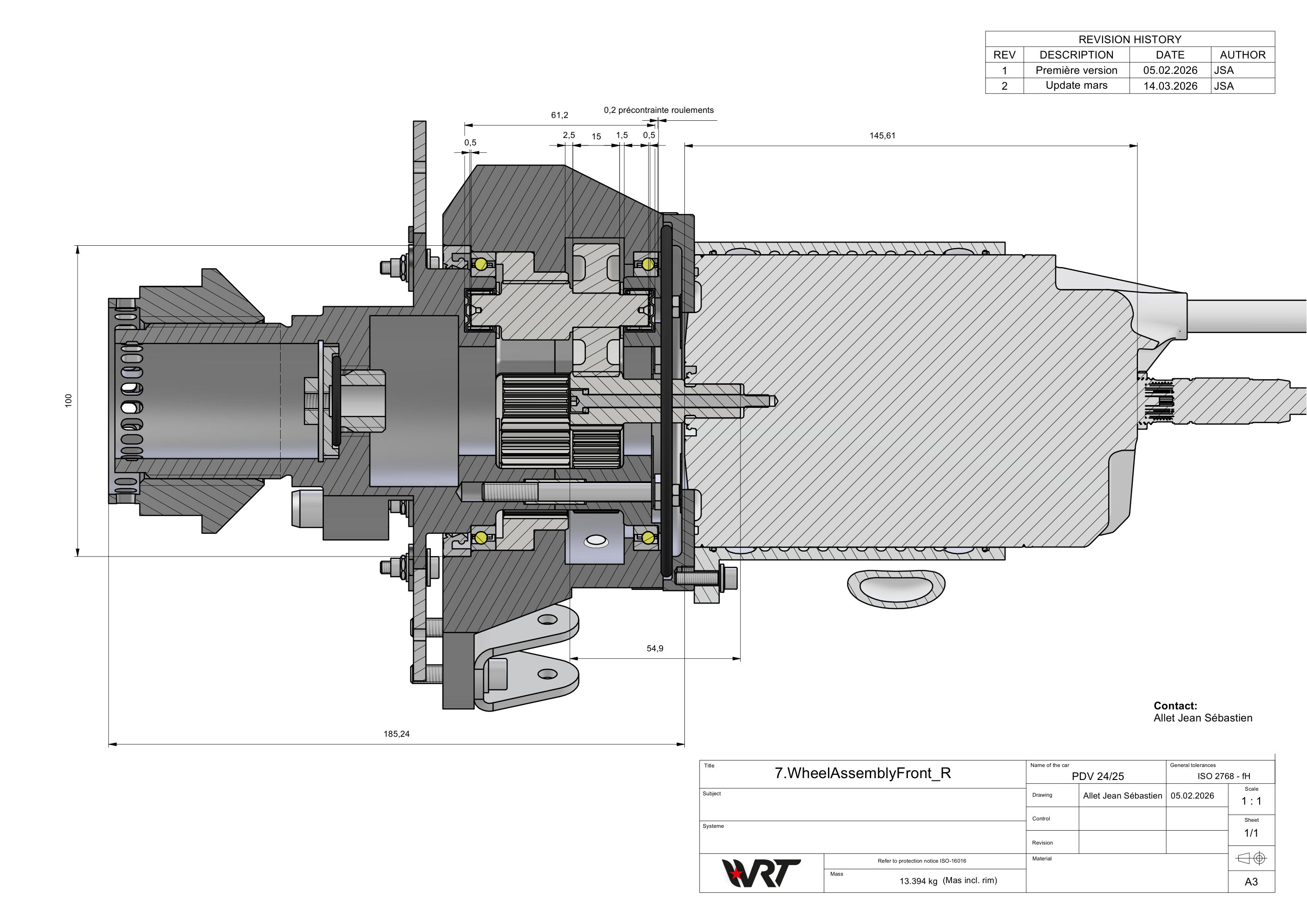
Section drawing of the front right wheel corner: wheel, gearbox and motor
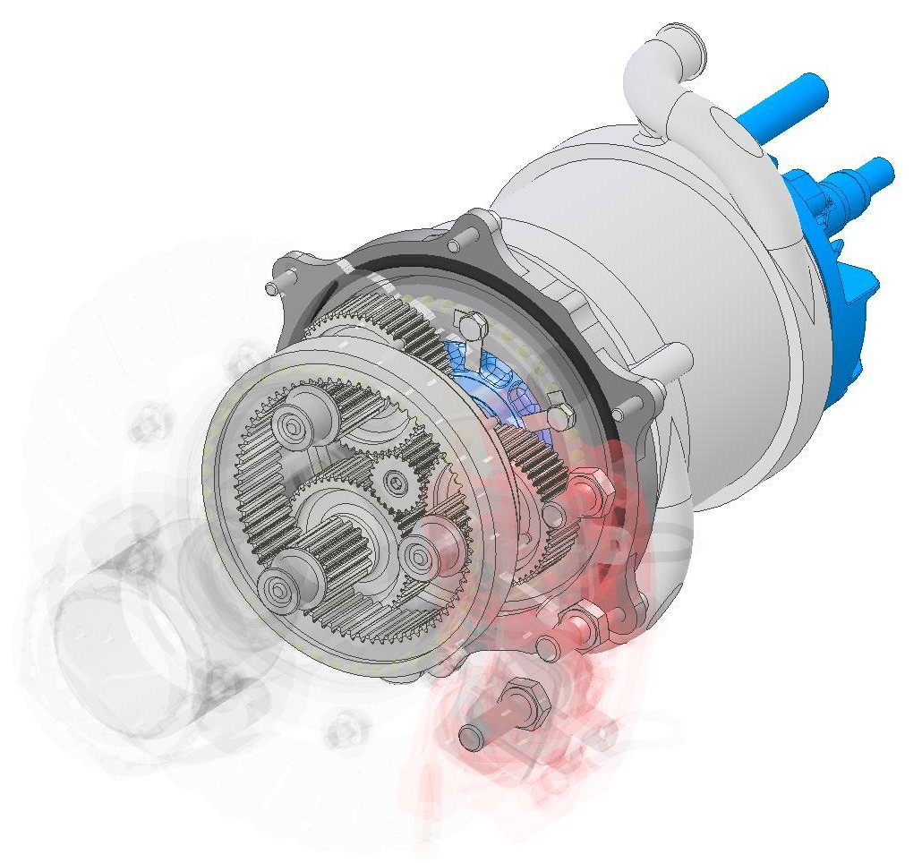
Cut-away CAD render of the stepped planetary gearbox on the motor

The solution

Small part, big job.

The motor spins fast with little torque, the wheel needs the opposite. My answer: a two-stage stepped planetary gearbox that turns one into the other, small enough to sit inside a 10-inch wheel.

Type
Stepped planetary, 2 stages
Motor in
Up to 20 000 rpm
Wheel out
Up to 403 Nm peak
On the car
4 gearboxes, one per wheel
Material
31CrMoV9 steel, nitrided 48 h
Tools
KISSsoft · Inventor

How it works

Watch it turn.

The motor drives the sun gear in the middle. Stage 1: the sun turns the three big planet gears. Stage 2: the small planet pinions on the same shafts roll inside the fixed ring and turn the carrier, which drives the wheel. Result: 12.6 times slower, with about 12.6 times the torque, minus small losses.

The 3D view needs WebGL, which this browser does not offer.

Slow motion ×1/100

  • Sun · input
  • 3 stepped planets
  • Ring · fixed
  • Carrier · output

Set the motor speed on the sun gear and see what comes out of the carrier. Same tooth counts as the real gearbox.

  • 6 000rpm, sun (input)
  • 476rpm, carrier (output)
  • 12.6: 1ratio

Drag the model to turn the view. Gears and the two-part carrier built from the manufacturing drawings. A quarter is cut away.

Design and build

From blank page to race car.

Four steps took it from the first calculation to four gearboxes on the car. I did all of them myself, except the machining.

  1. Calculation

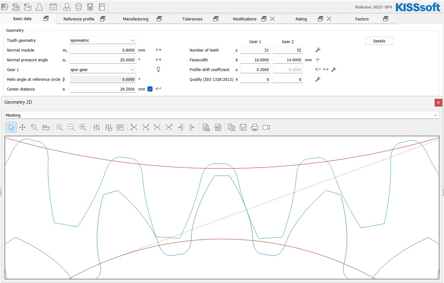
    I sized both gear stages in KISSsoft for tooth root and flank strength. Tooth counts with no common factor, so every tooth meets every tooth of its mate and the load spreads evenly.

    Screenshot of the stage 1 gear pair in KISSsoft

    Software

    • KISSsoft
  2. CAD and drawings

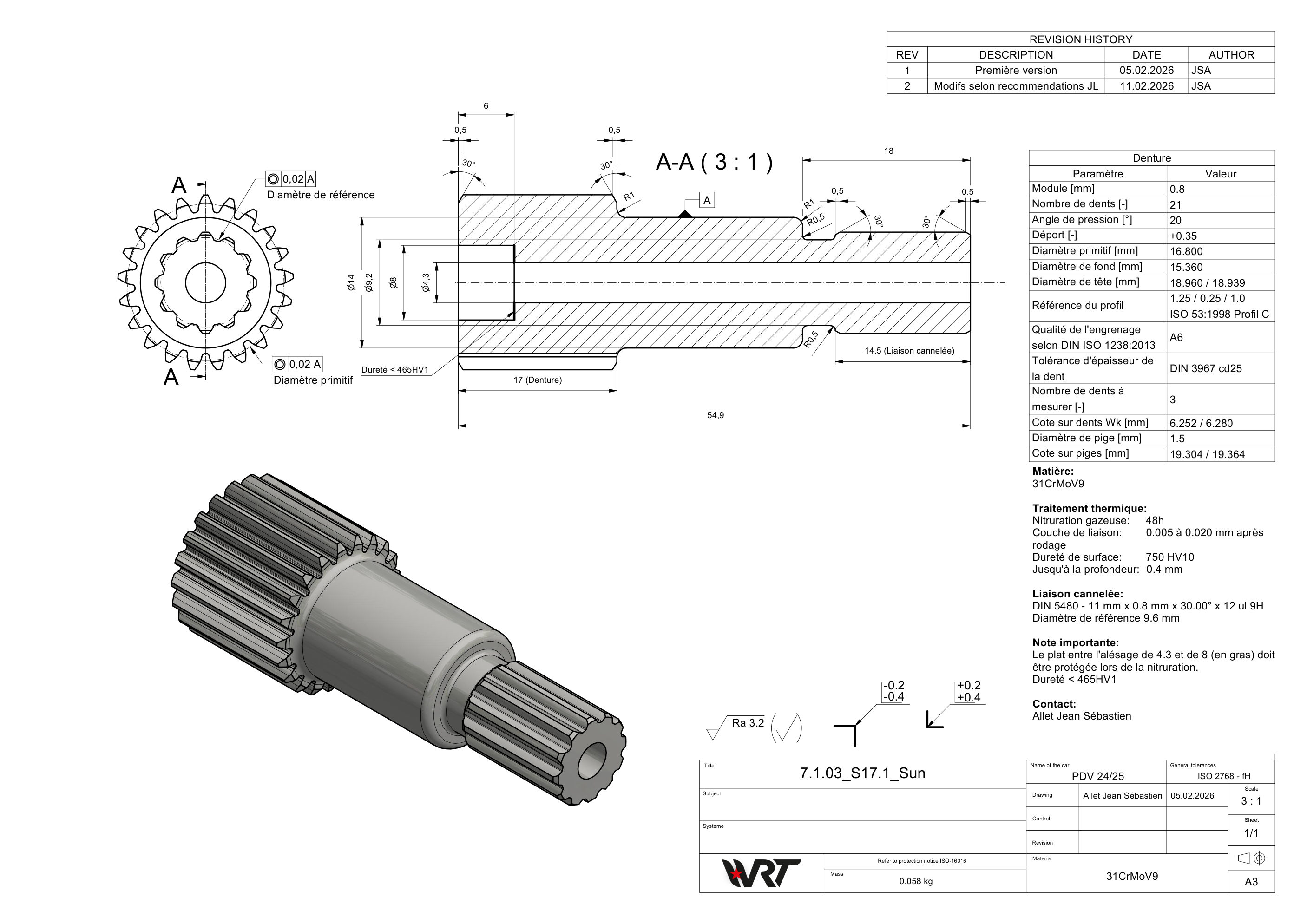
    Every part modelled in Autodesk Inventor, then a full set of manufacturing drawings. The new motor has a female output, so I gave the sun gear a spline (DIN 5480) that plugs straight into it.

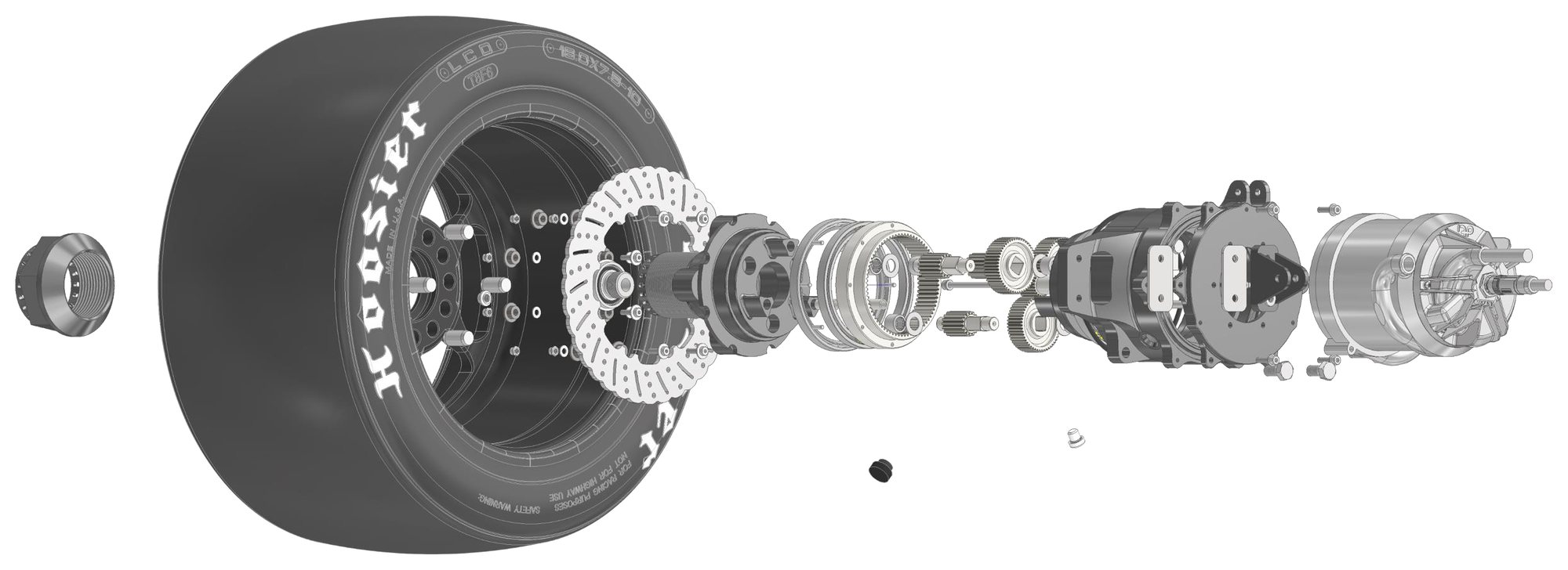
    Exploded view of the wheel corner

    Software

    • Inventor
    • Vault
  3. Manufacturing

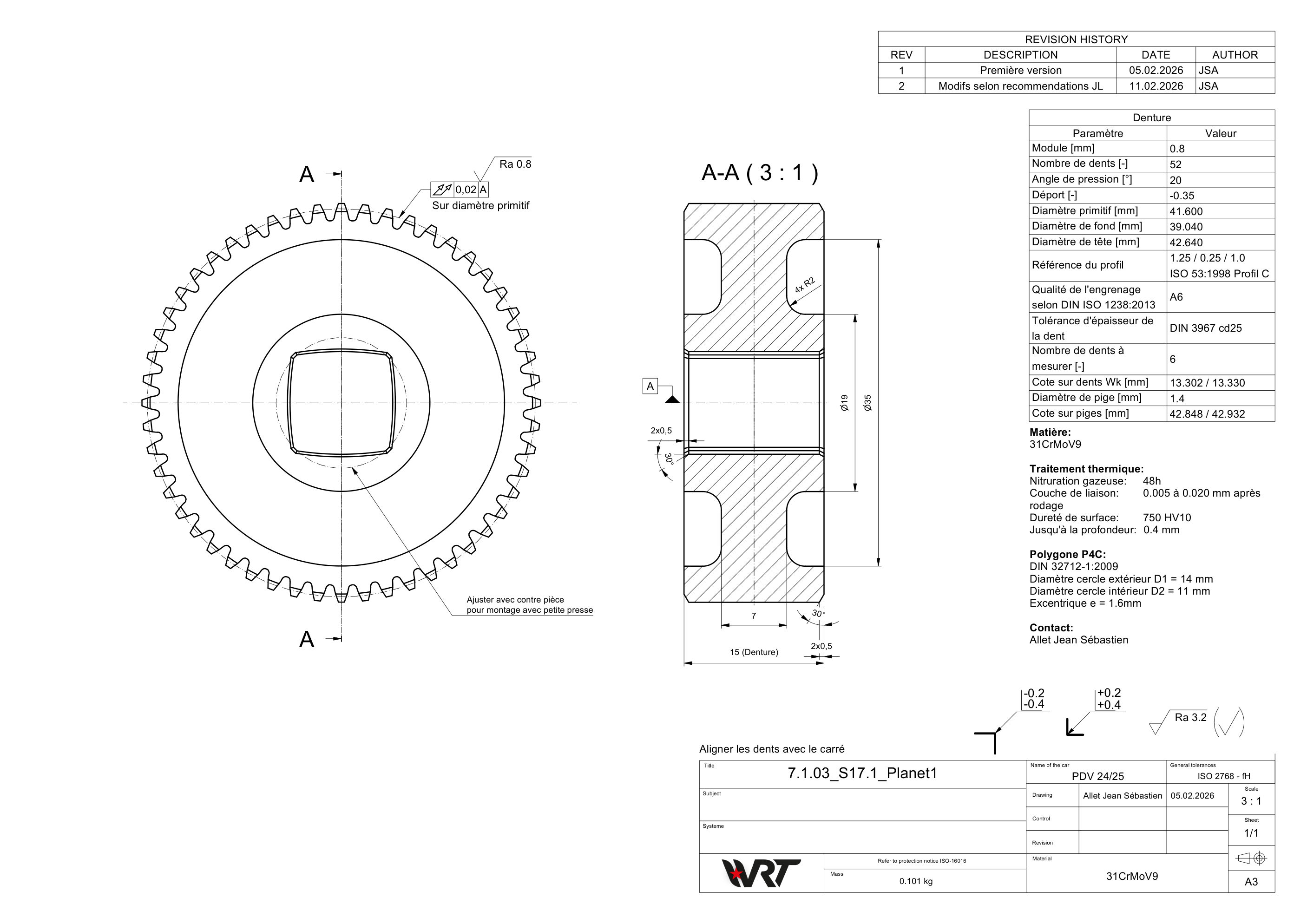
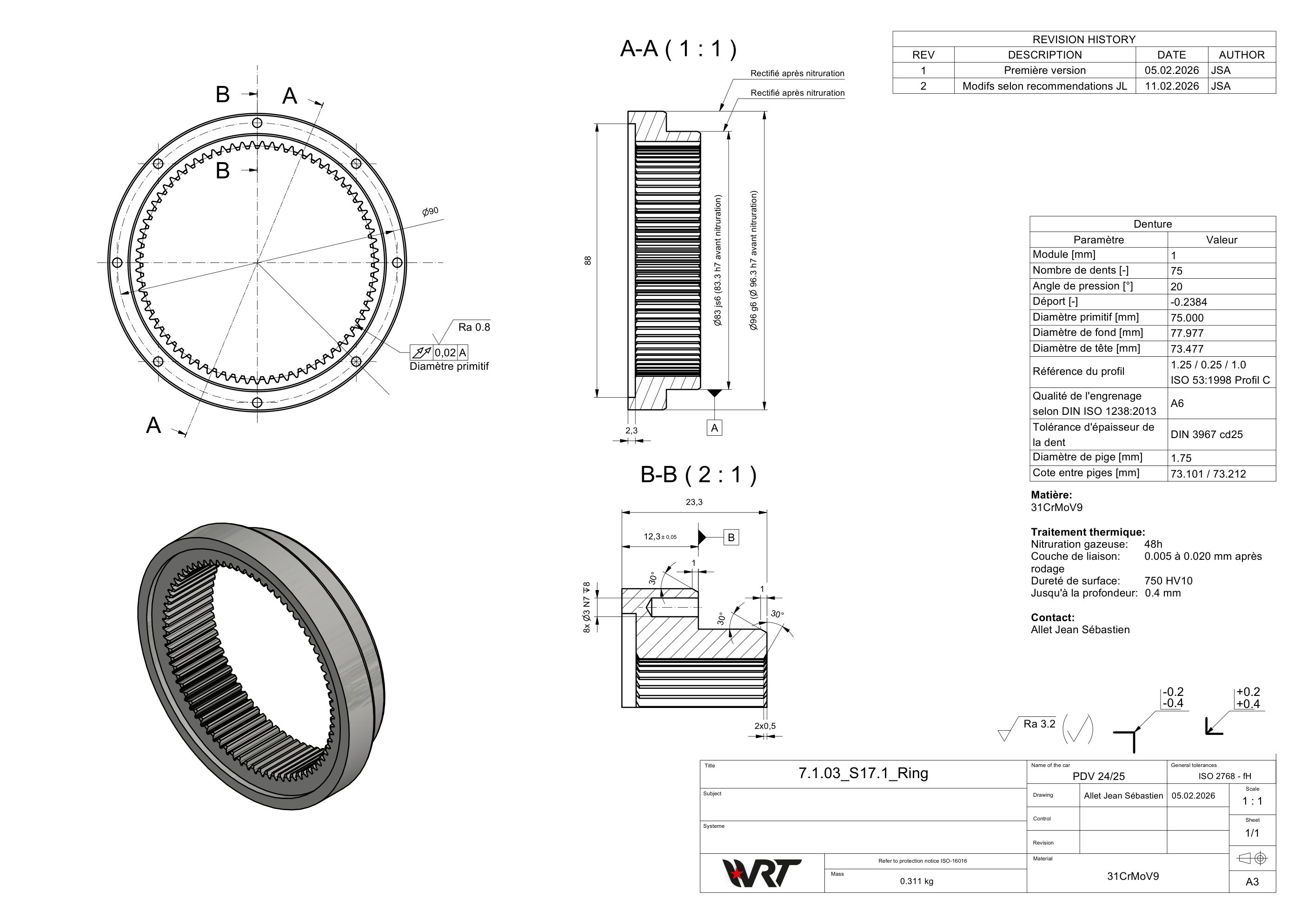
    Jacquier & Luisier SA in Valais machined the parts. Their machinists went through my drawings with me before cutting any steel. Working with a real company like this was one of the best parts of the project.

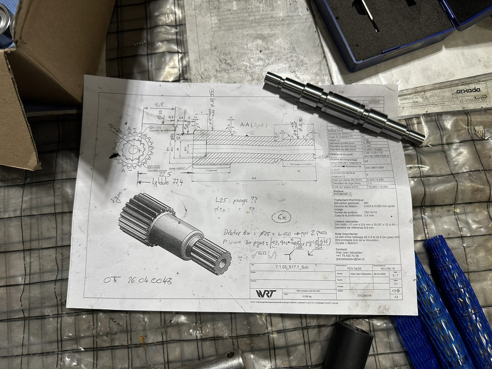
    Drawing of the sun gear with the machined part lying on it
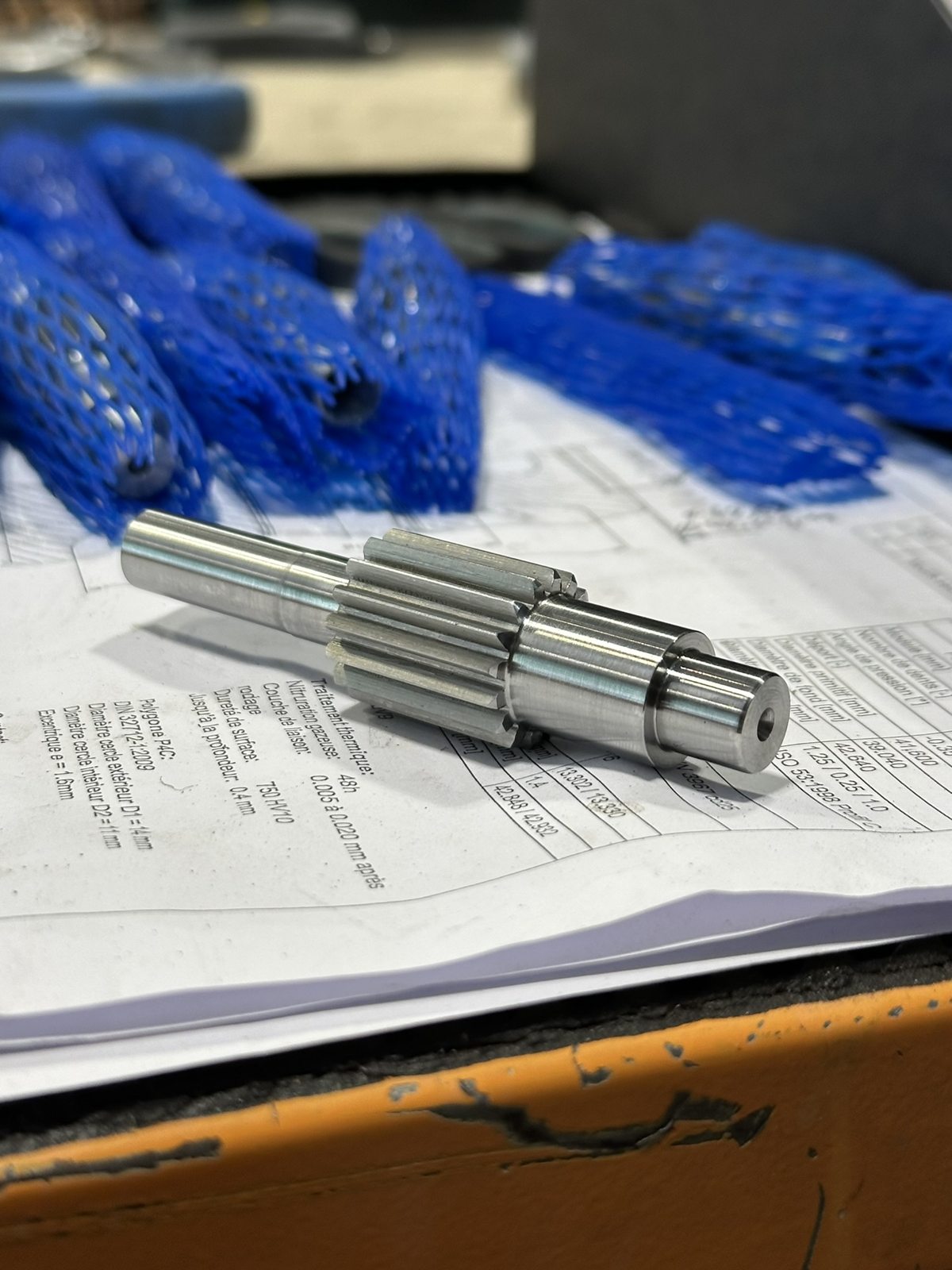
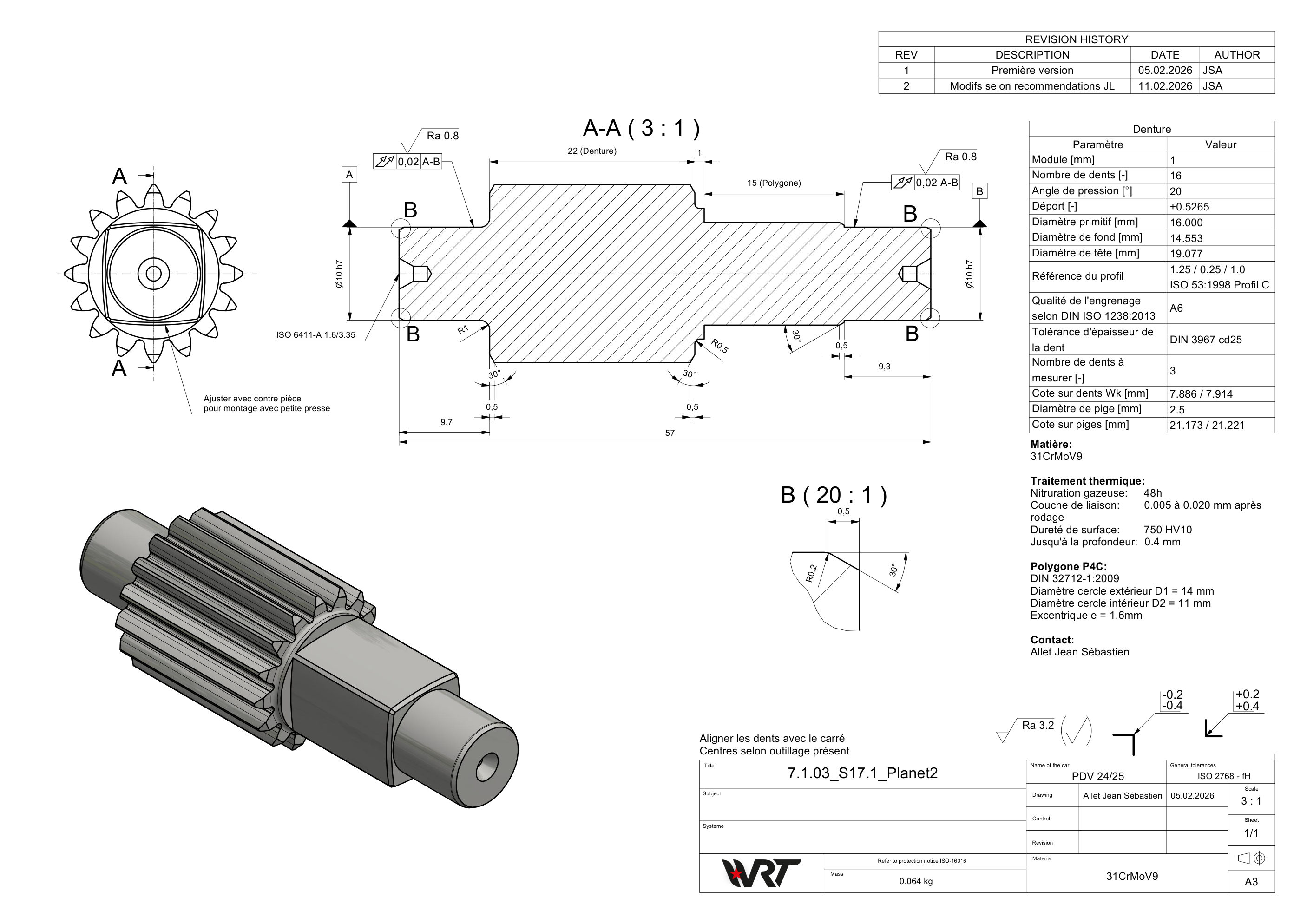
    Machined planet shaft on its drawing
  4. Assembly and racing

    I assembled all four gearboxes myself and was on site at Formula Student Germany and Austria.

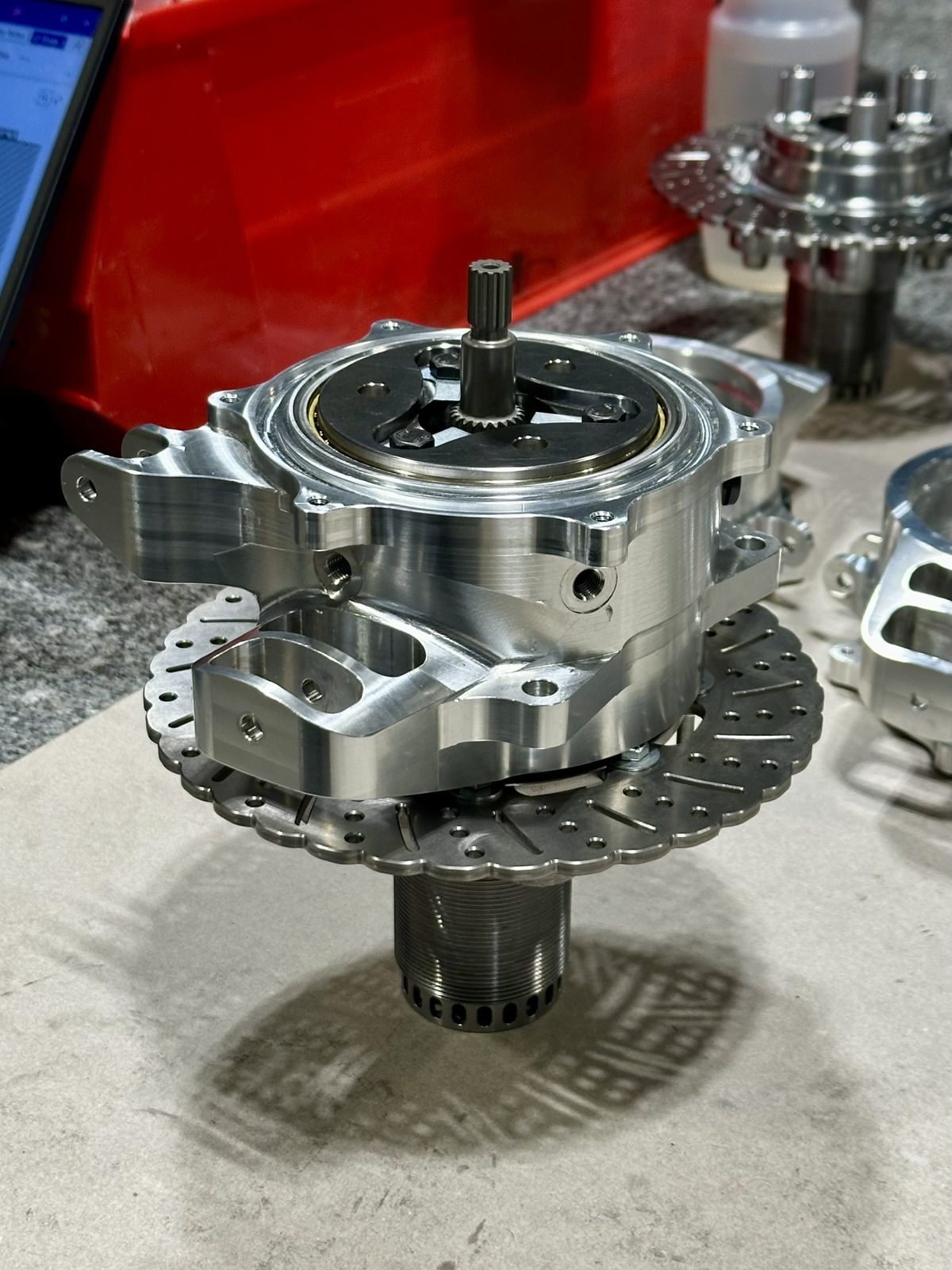
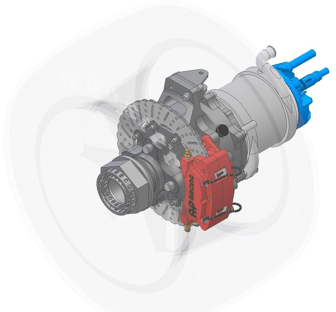
    The machined upright with the gearbox, hub and brake disc

Results

It raced the whole season.

Then the real test: four competitions across Europe in 2026: Formula Student Germany at Hockenheim, Austria at the Red Bull Ring, Switzerland and France. All four gearboxes ran the whole season.

  • Formula Student Germany
  • Formula Student Austria
  • Formula Student Switzerland
  • Formula Student France